Advanced Magnetic Propulsion Systems for Flying Vehicles
(bilingual: in English
and Polish )
Updated:
7 October 2013
Click "X" or "No" on e.g. messages of supposed errors, or on advertisements, if these try to interrupt your viewing of this web page.
Here
is the list of all web pages which should
be available at this address (i.e. from this
server), arranged by language (in 8 languages).
It represents a more frequently updated version
of "Menu 1". Choose below the page that interests
you by dragging scroll bars, then click on this
web page to run it:
(The same list can also be displayed
from "Menu 1" by clicking
Menu 2.)
Here is the list of addresses of all
totaliztic web sites that still worked
at the date of the most recent update
of this web page. At each of these addresses
should be available all totaliztic web pages
listed in "Menu 1" or
"Menu 2",
including also their different language versions
(i.e. versions in languages:
Polish, English, German, French, Spanish, Italian,
Greek or Russian.) Thus firstly select
the address which you wish to open by dragging
scroll bars in small window below, then click on
this address to run it. When opens the web
page which represents this address, then choose
from its "Manu 1" or
"Menu 2"
the web page which interests you and click on it
to view that page:
(The above list can also be displayed
from "Menu 1" by clicking
Menu 4.)
It is enough to venture at a street of any city to realise
that our present propulsion systems are NOT
going to take us far. After all, they stink out our
natural environment, persecute us with their noise,
consume the remains of natural resources that our
mother Earth offered to us, and it is increasingly
difficult to park them, to store them, and to dispose
them. So there must be a better way to solve our
transportation problems. This better way is called the
Magnocraft.
Soon such Magnocrafts are going to replace NOT
only our present cars, but also all our space vehicles.
This web page explains how exactly we learned
that Magnocrafts for sure are to arrive soon, what
evidence confirms that Magnocrafts are technically
feasible, what attributes these Magnocrafts are to
display, and what other vehicles that are even more
advanced are to come after these Magnocrafts.
Part #A:
Introductory information of this web page:
#A1.
What are goals of this web page:
The main goal of this web page and the
body of evidence which I present here,
is to document and to explain to the reader
entirely new propulsion systems that soon
are to be completed on our planet.
Part #B:
The incoming era of designing new propulsion systems instead of inventing them:
#B1.
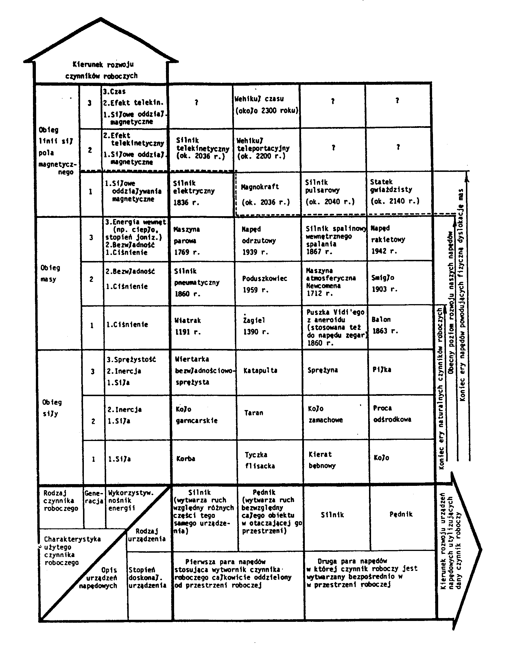
The "Periodic Table" for Propulsion Systems:
Do you remember how subsequent chemical
elements were discovered. Well, initially chemists
kept discovering them by chances. Then a
great Russian scientist and thinker was born,
named Dmitry Ivanovich Mendeleyev
(1834 - 1907). He discovered that subsequent
elements fit nicely into a tidy table, which we
call the Periodic Table of the Elements
or the "Mendeleyev's Table". When this table
was created, further discoveries of chemical
elements become intentional. This is because
the "Mendeleyev's Table" was telling people
which chemical elements still remain undiscovered,
and what their properties are. So by following
hints that result from this table, remaining
chemical elements could be discovered
and described quite quickly and effectively.
As it turns out exactly the same happens with
inventions of new propulsion systems and new
propelling devices. Initially these were invented
by chances. And so in this manner James Watt
(1736 - 1819) invented a steam engine, while
Rudolf Diesel (1858 - 1913) invented a diesel
engine. But in 1972 an equivalent of the
Mendeleyev's Table was discovered also for
propulsion systems. This equivalent takes a
shape of the
Periodic Table for Propulsion Systems -
shown and explained comprehensively in chapters
B and LA (volumes 2 and 10) of the newest scientific
monograph [1/5],
as well as on the Figure below. The general principle
on which this table was designed is called the "Cyclic
Principle" (thus the "Periodic Table for Propulsion
Systems" can also be called the "Cyclic Table").
In exactly the same
way as the "Periodic Table of the Elements"
allows to discover intentionally all subsequent chemical
elements, also the "Periodic Table of Propulsion Systems"
allows to invent intentionally new propelling devices and
new vehicles. This is because it puts all possible propelling
devices into a tidy order, thus allowing to reason about
their future design, principles of operation, and displayed
properties. So this new table opens for us the doors for
an easy and effective inventing of all propelling devices
that humanity is going to build in the future. Here is how
this unique table looks like:
The "Cyclic Table" as well as the "Mendeleyev's
Table" are consequences of a high symmetricity
with which God created our physical world, and
which the French researcher named Louis De
Broglie formulated into his "Principle of the Symmetry
of Nature" - described, amongst others, in subsection
H6.1 from volume 4 of my newest
monograph [1/5],
and briefly summarised, amongst others, in item
#B1 of the totaliztic web page named
antichrist.htm.
According to this principle, in our universe
everything is strikingly symmetrical in many
ways. DeBroglie's symmetry principle provided
philosophical and scientific foundations, which
allow us to understand a number of natural
phenomena, thus opening them for explorations,
discoveries, formulation of new theories,
completion of new devices, etc. For example:
the Periodic Table of the Elements (also called
the Mendeleyev Table), the existence of a mirror
duplicate for each elementary particle (e.g.
electrons and positrons, protons and antiprotons),
and the similarities between atoms and solar
systems - all these document the symmetry
existing in the structure of matter. The similarities
between equations that describe different physical
phenomena (e.g. Navier-Stock's equation
describing flow of fluids and Laplace's equation
describing heat transfer) express symmetry in
the laws of nature. In turn the technological
correspondence between e.g. pumps and
hydraulic motors, or electricity generators
and electric motors, reflect the symmetry
in the operation of technical devices.
Further information about how the "Periodic
Table of Propulsion Systems" (or "Cyclic Table")
converts the previous "inventing" of new propelling
devices into a process of scientific synthesizing
of these inventions, provides subsection LA1
from volume 10 of the newest
monograph [1/5].
The theoretical explanations are supported in
there with examples of scientific synthesizing
of inventions of a
telekinetic vehicle and a
time vehicle
(i.e. Magnocrafts of the second and third generation).
Fig. #1
(Tab. B1 in [1/5]): The "Periodic Table for
Propulsion Systems". It is like an equivalent
of the "Mendeleyev's Table" (also called the
"Periodic Table of the Elements"). Only
that instead of chemical elements, the above
"Cyclic Table" reveals symmetries and
similarities that exist in the principles of
operation, designs, and dates of discoveries
of subsequent propelling devices.
This is why the "Cyclic Table" allows us to
predict the operation, design, and properties
of all future propulsion systems still awaiting
to be invented and build on the Earth. Actually,
it allows to even develop a computer program
that is going to tell future inventors which
propulsion systems are still awaiting for
someone's creative interest. The effect
of formulation of the above "Cyclic Table"
was, that the author of this web page with
the aid of this table was able to develop a
principle of operation and design of initially
a starship called the
Magnocraft,
and later also the principle of operation and design of a
time vehicle.
This unique table is described thoroughly
in chapter B (volume 2) of the newest
monograph [1/5],
as well as in older monographs [1/4], [1e], and [2e].
It is also published and explained in monographs
[5/4], [5/3], [6], and [6/2].
An intriguing phenomenon which was revealed
to me during my testing of the dissemination of the
above "Cyclic Table" through the internet, was that
someone highly influential seems to block and
sabotage the viewing this table by readers - as
this explained e.g. in item #J2 of the web page named
faq.htm.
For example, in order the reader could analyse this
table thoroughly, in the internet is disseminated an
enlargement of it prepared in the safe format PDF -
about which format it is known that it was intentionally
so designed that computer viruses were unable to
attach themselves to it. For example, just such an
enlargement of this table in the safe format PDF
is available, amongst others, on this web site
(click on this link to call it up),
as well as it is also available on other totaliztic
web sites - for example see the address
http://energia.sl.pl/14/14_tab_b01_e.pdf.
However (as I noted this during testing my web pages),
when one tries to download and view this enlargement
of the "Cyclic Table", unexpectedly appears a message
with some mysterious warning - which I am unable to get
rid of in any way. There is also no way to explain this
message - taking under consideration that texts in PDF
format are NOT carriers of any computer viruses, and
also that apart from the above table I never met in internet
any other text in the PDF format that would generate
just such, or a similar, mysterious message. Thus,
e.g. apart from an intentionally-discouraging action
of someone sufficiently influential to be able to spread
this messages onto the entire internet, and specifically
attach it to my table, I do NOT have any explanation
regarding where this mysterious message comes from.
Perhaps the reader could help me to find out what
causes this message and how I can get rid of it!
I should add here, that in order to view the enlargement
of the above table disseminated in the safe format
PDF, one needs to either (1) open this enlargement
from a commonly accessible internet address which
clearly indicates that the table is available in the safe
format PDF - e.g. from the address
http://energia.sl.pl/14/14_tab_b01_e.pdf
(for the increase of safety and peace of mind, this
opening can be carried out e.g. through a "firewall"
that exists in a majority of Cyber Cafes, or through
some software system which checks and filters for
computer viruses everything that passes through it -
such as is e.g. almost every email system), or (2)
click on the following button
which also allows to download it in the safe format
PDF from this web site, or (3)
to click on the above "Cyclic Table" and then follow instructions that are to appear -
as this would also download it in the safe format PDF.
#B2.
"Motors" versus "propulsors":
Before I explain how works
the "Periodic Table for Propulsion Systems", firstly I
need to explain scientific foundations behind two most
basic terms used in research on propelling devices. These
two terms describe two basic kinds of propelling devices,
namely the so-called "motors" and the so-called "propulsors".
Motors produce only a relative motion of one
group of parts of a given machine, in relationship to other
group of parts of the same machine. This means that motors
are practically unable to produce the absolute motion of
entire objects in relationship to the environment of these
object, although they frequently provide mechanical motion
that is later used to create such an absolute motion. As
an example consider a car, in which the engine is a typical
"motor". Everyone knows that the engine from a car DOES NOT
produce the motion of the entire car along a road - but
these are wheels which produce this motion. The engine from
a car supplies only the mechanical energy to wheels. So
a car is a machine which contains both, a single motor (i.e.
the car's engine) which causes the relative rotation of wheels
in relationship to the car's body, and four propulsors (i.e.
four wheels) which produce absolute motion of the car along
the road. Similarly is with a boat. A "motor" in a boat
only reassures the relative rotation of propeller, while
the absolute motion of the entire boat is formed by this
propeller, not by the motor.
Devices which produce
an absolute motion of entire vehicles in the surrounding
environment are called propulsors. Examples of
propulsors include: a propeller in an aeroplane, helicopter
blades, jet engine, rocket engine, hovercraft outlets,
wheels, propeller in a boat, and many more. Notice that
propulsors must be distinguished from so-called linear
motors. For example railway locomotive is just simply
a linear motor, not a propulsor. This is because propulsors
produce an absolute motion in the natural environment. In
turn linear motors produce only a relative motion in relationship
to one of their part (e.g. a "rail") that is extended at large
distance.
#B3.
How the Periodic Table for propulsion systems is constructed:
The general principle on which the Periodic
Table for Propulsion Systems is constructed,
is based on my discovery that there is a
number of very strict relationships between
inventions of motors and inventions of propulsors.
There is several such relationships, which
are described comprehensively in chapters
B and LA of
monograph [1/5].
These relationships decide about each invention
of a new propelling device. Because of them
it is possible to predict exactly (a) which next
propulsion system is going to be invented on
Earth, (b) when the invention of this next propulsion system is going to
occur, (c) how this new propulsion is going to operate, and (d) what
phenomena and principles of operation this new propulsion system is
going to utilise for the operation. In order o keep this web page brief,
I am going to explain here only the first and the most important one,
out of these numerous relationships expressed in the Periodic Table.
This relationship states that each motor must have a corresponding
propulsor. In order to explain here the technical interpretation
of this statement, it practically means that propulsion systems are
always invented in pairs. Firstly a motor is invented, and then this
motor is followed by a corresponding propulsor. For example, if
someone invents a "motor" such as let say an "internal combustion
engine" used to propel our cars, soon afterwards someone else invents
also an almost identical propulsor such as an engine for "space
rockets". (Notice that the basic part of a space rocket, namely
the thrust outlet, is almost like a cylinder used in internal
combustion engines, only that the piston is removed from this
cylinder and replaced by the rocket's outlet.) If we review
all "motors" invented on Earth so-far, it turns out that each one
of them has a corresponding propulsor already working - for details
see the Periodic Table shown above. This means that practically for
almost all of them the inventions of mutually corresponding pairs
were completed. And so, for example a motor which we know as a "windmill",
has a corresponding propulsor in the form of a "sail". A motor in the
form of an "internal combustion engine", has a corresponding propulsor
in the form of a "space rocket". A motor in the form of "gas turbine"
has a propulsor in the form of a "jet engine". Etc., etc.
#B4.
Why the Periodic Table for propulsion systems indicates that the next most
important new propulsion system build on the Earth will be the space vehicle named the
Magnocraft:
The Periodic Table indicates that, except
for one, almost all motors systems completed
on the Earth already have the corresponding
pair in the form of a propulsor that works
on the same principles of operation like
a given motor. This single motor which is
already invented, but which does not has
a corresponding propulsor, as yet, is a
common "electric motor". (More strictly
we should call it a "magnetic motor",
because the working medium utilised in
it is the magnetic field.) So according to
the Cyclic Principle soon we must expect
a propulsor to be build on Earth, that
represents a pair for electric motors.
This new propulsor is to be utilised for
propelling a space vehicle named the
"Magnocraft".
The Periodic Table indicates that the
Magnocraft is going to be build on Earth
not later than by the year 2036.
#B5.
According to the Cyclic Principle three different generations of
Magnocraft
are to be completed at the Earth in the not-too-distant future:
The Periodic Table for propulsion systems
indicates, that after people build the first
magnetically propelled Magnocraft, still
even more advanced vehicles are to
come to Earth later. These more advanced
vehicles include a "telekinetic Magnocraft"
and also a "Time vehicle". Because
both these more advanced vehicles are
to use a very similar propulsion system
as the Magnocraft does, and also because
they are to keep the Magnocraft's general
shape and design, they are called the
Magnocraft of higher generations.
Telekinetic Magnocraft represent Magnocraft of the second generation,
while time vehicles represent Magnocraft of the third generation.
Telekinetic Magnocraft is going to fly through space instantly, means
with infinitively high speed. In turn the time vehicle is going to be able
to shift itself and its crew forth and back in time. Thus it will move
people either to the future or to the past. Principles of instant telekinesis,
on which the telekinetic Magnocraft is going to operate, are summarised
briefly on separate web sites devoted to telekinesis. An example of such
web site is
telekinesis.htm.
In turn the operation of time vehicles is summarised on the web site
timevehicle.htm.
But the most comprehensive description of both these futuristic vehicles
is provided in chapters LC and M of the newest monograph [1/5] available
free of charge via menus from this web page.
Magnocraft of the first, second, and third generation
display an interesting property, which in chapter
B of monograph [1/5] is described under the
name of "omnibus trend". The omnibus
trend is simply an ability of more advanced vehicles to use the mode of
flight characteristic for less advanced vehicles. This trend is already
being implemented on Earth, as for example a space shuttle typically can
fly in as many as three different modes, namely as (a) a space rocket,
(b) a glider, and (c) an inertial satellite. This particular trend is going
to even deepen for the Magnocraft. Therefore for example the Magnocraft
of the second generation will be able to fly in two different modes of
operation, as (a) a magnetic vehicle identical to the Magnocraft of the first
generation, and as (b) a telekinetic vehicle. In turn Magnocraft
of the third generation will be able to fly in three different modes of
operation, namely as (a) magnetic vehicles identical to Magnocraft
of the first generation, as (b) telekinetic vehicles, and as (c) time
vehicles.
The extremely interesting are telekinetic
vehicles or Magnocraft of the second generation. The analysis of the
Periodic Table reveals that they will be able to fly through space with
infinitive velocities. So practically they can reach destinations located
in other galaxies in exactly the same moment when they leave Earth. This is the
reason why they are going to allow humans for intergalactic travel.
They also are going to allow flights through solid matter, as well as they
may become invisible to human sight. For this reasons telekinetic UFO vehicles
can fly directly to our houses and we even do not notice them. More information
about principles used by telekinetic vehicles is provided on web pages on
telekinesis, e.g. on:
telekinesis.htm.
Part #C:
Future propelling devices indicated by the "Periodic Table" for propulsion systems:
#C1.
The discoidal
Magnocraft
of the first generation:
The most important vehicle of our future,
that according to the Periodic Table is soon
going to be build on Earth, is the interstellar
flying vehicle named the
"Magnocraft".
The name "Magnocraft" is simply assigned
to a human-made advanced space vehicle,
which utilises magnetic propulsors for
thrusting through the space. Because soon after
this first Magnocraft, even more advanced magnetic
vehicles are going to be build on Earth, this
most basic magnetic vehicle is also called the
Magnocraft of the first generation.
What is most interesting about this magnetic
space vehicle of the first generation, that it is
already able to accomplish speeds close to
the speed of light. So it will make the
interstellar travel possible for people.
Here is how this Magnocraft is going to look like:
Fig. #2 (C1(b) in [1/5]):
Appearance of the K3 type Magnocraft of the first
generation (click on it to see it enlarged).
The
Magnocraft
is a discoidal space vehicle which flies silently with
speeds of light. It is propelled magnetically by so-called
Oscillatory Chambers,
* * *
Notice that you can see the enlargement
of each illustration from this web site. For this it suffices to click
on this illustration. Furthermore, most of the internet browsers that you may
use, including the "Internet Explorer",
allow also to download each illustration
to your own computer, where it can be looked at, reduced or enlarged to the
size that you may want, or printed with your own graphical software.
#C1.1.
Design and main components of discoidal
Magnocrafts:
The Periodic Table hints to us, that the
propulsors utilised in the
Magnocraft
are to represent a "pair" for a common electric
motor. So the same as in electric motor the propelling forces
are produced due to magnetic attraction and repulsion, also in
the Magnocraft these forces of magnetic attraction and repulsion
are going to allow to fly through the space. So how the Magnocraft
is going to work. Well, we know that every heavenly body, including
our Earth, Sun, and Galaxy, generates its own magnetic field. Thus
each planet and each star is simply a huge natural magnet. Therefore,
if we build also another powerful magnet (lets us call this our own
technical magnet with the term "magnetic propulsor" or
"Oscillatory Chamber")
than this our own magnet can repel itself from Earth,
Sun, or Galaxy. Thus, if it is powerful enough, it is able to
produce forces of repulsion that are able to lift an entire flying
vehicle into space. Therefore, if we build an appropriate configuration
of such magnetic propulsors, we can obtain a spaceship, or a flying
vehicle, that is going to fly through space, just on simple principles
of magnetic repulsion and attraction. Here is how such a Magnocraft
needs to be designed:
Fig. #3 (C1(a) in [1/5]):
Design and main components of discoidal Magnocrafts
of the first generation. You can notice that
in order to fly through the space, the
Magnocraft
needs to have a single powerful cubical "magnet"
located in the centre of this spaceship - lets call
this cubical magnet the main propulsor
or the "main
Oscillatory Chamber"
(see "M" on the Figure above). By repulsive interaction
of this cubical propulsor M with the field of Earth,
Sun, or Galaxy, the lifting force is formed, which
propels the Magnocraft upwards. In turn on the
peripherals of the Magnocraft, a ring of at least
8 side propulsors is assembled - on the Figure
above shown as cubical "magnets" located inside
of spherical casings and marked as "U" and "V".
These side propulsors attract themselves to sources
of the environmental magnetic field (i.e. to sources
of Earth's, Sun's, or Galaxy's magnetic field), thus
producing the stabilisation forces. These stabilisation
forces hold the rim of bell-shaped Magnocraft in
stable position, thus fixing the orientation of the
Magnocraft in space. They also allow Magnocraft
to descend whenever it is necessary.
#C1.2.
Propelling unit and principles of flights of discoidal
Magnocrafts:
One magnetic propulsor alone is not able to provide adequate flight and
manoeuvrability for the Magnocraft, just as a single wheel is not sufficient
to construct a motor car. Therefore in the spaceship described here, a
number of such propulsors strictly cooperating with one another must be
utilized. The optimal configuration of propulsors which is able to fulfil all
the requirements of flight and manoeuvrability is called here the "magnetic
propelling unit". Such a propulsion unit used in the Magnocraft is shown
in "Fig. #4" below (to simplify the explanations that follow, it is illustrated
as flying above of the Earth's north magnetic pole). The main attribute
of this unit is that it employs a minimal number of magnetic propulsors,
providing at the same time the maximum range of operational possibilities.
Therefore this unit, after only a slight modification, is also utilized in the
"Four-Propulsor Spacecraft" (refer to chapter D in [1/5]) and also in
"Personal Propulsion System" (refer to chapter E in [1/5]).
The configuration of this unit is based on the shape of a bell. In turn a bell
is the most self-stabilising form out of all simple shapes known to physic.
The basing of this configuration on the shape of a bell results from the fact,
that in such propulsion unit the distribution of lifting and stabilizing forces
resemble a bell shape, with a single holding point located at the centre,
and a ring of stabilizing weights suspended below this point at even distances.
(It is well known from mechanics, that bells represent the physical form
that is considered able to provide optimal self-stability in space, while after
being put out of balance it always returns on its own to the previous position
of stability.)
Let us now analyze the main components and operation of the magnetic
propulsion unit. It consists of two different kinds of propulsors, i.e. a single
main propulsor (marked "M" in "Fig. #4") located in the centre, and a
number of side propulsors (marked "U, V, W, X" in "Fig. #4") distributed
evenly around a lowered ring. According to the condition explained in
subsection G4.2 of [1/5], the total number "n" of side propulsors must
always be a multiple of four. The main propulsor is usually oriented so
as to be repelled by the Earth's magnetic field. (The introductory part
to subsection G1 in [1/5] explains that on the north magnetic pole of Earth,
such a repulsive orientation of propulsors can be obtained when their
north "N" pole is pointed downwards.) The side propulsors are usually
oriented so that they are attracted by the field of the Earth.
By increasing the flux produced by the main propulsor (M) oriented in
such a repulsive manner, an increase in the repulsion force "R" is achieved.
At the moment when the repulsion force overcomes the gravitational pull,
the propulsor (M) begins to ascend, lifting up the entire propulsion unit.
If the main propulsor would operate alone, then its flight would be disturbed
by the magnetic torque which would tend to turn around the propulsor's
magnetic orientation so that attraction would replace repulsion. Thus, to
compensate for the effects of the environmental magnetic torque trying
to turn the main propulsor around, additional stabilizing side propulsors
"U, V, W, X" are necessary. Their magnetic orientation opposes that of
the main propulsor (M), i.e. when the main propulsor is to be repelled,
side propulsors are to be attracted by the environmental magnetic field.
A possible configuration of such side propulsors is illustrated in "Fig. #4".
These side propulsors give flight stability to the whole propulsion unit.
By appropriate adjustment of the produced fluxes, the side propulsors
can enforce the balanced orientation of a craft in whatever attitude and
position the crew requires.
There is a bit more to the complete operation
and design of the Magnocraft. After all, this
vehicle can form many more interactions and
phenomena, than these basic ones described
above. Fortunately, these further principles of
the starship, can be learned from chapter G of
monograph [1/5],
and also from other publications that are
downloadable free of charge from this web
site. Some of these further details are
summarised on web pages named
magnocraft.htm and
military_magnocraft.htm
which are entirely devoted to the description
of this space vehicle.
Fig. #4 (G3 in [1/5]):
The propelling unit utilised in the Magnocraft
of the first generation. (Click on this drawing
in order to see it enlarged.)
This unit is illustrated as hovering above the northern (N) magnetic
pole of Earth. Shown are: "M" - the single main propulsor involved
in a repulsive force interaction "R" with the Earth's magnetic field
(marked "M" from the word "main" propulsor); "R" - forces of magnetic
repulsion (marked "R" from the word "repulsive" interaction);
"U, V, W, X" - eight side propulsors oriented so as to attract "A"
the environmental magnetic field (marked "U, V, W, X" for emphasizing
their mutual phase shifts by 90 degrees); "A" - forces of magnetic
attraction. Note that in subsequent types of Magnocraft the number "n"
of side propulsors is described by the equation: n = 4(K-1). Thus the
number n = 8 side propulsors has only the Magnocraft type K3.
Each of these propulsors consists of a twin chamber capsule
(formed from one inner and one outer Oscillatory Chamber -
as illustrated in Figure F5 of [1/5]) assembled inside a spherical casing.
Through an appropriate synchronization of the field pulsations in the
side propulsors, a whirling magnetic field can be produced by this unit.
Symbols: N - north magnetic pole (i.e. the "inlet" pole "I" as explained
in subsection G5.2 of [1/5]), S - south magnetic pole(i.e. the "outlet" pole
"O" - as explained in subsection G5.2 of [1/5]), 1 - frame which joins
the propulsors together; d - the maximal distance between the centres
of any two side propulsors located diagonally opposite from each other
in the unit (this vital distance "d" represents also the "nominal diameter"
of rings burned by side propulsors during landings of the Magnocraft;
it can be measured on landing sites of these vehicles - for details see
Figure G33 in [1/5]); h - the height of the centre of the main propulsor
above the bases of the side propulsors; R - the force of magnetic repulsion;
A - the force of magnetic attraction.
#C2.
Flying configurations coupled together during flights from discoidal
Magnocrafts:
One of the most important attributes of the Magnocraft's propulsors is that they allow for easy and complete control over the produced output and over the orientation of their magnetic poles. Therefore, independently of their propelling functions, these propulsors can also be used as coupling devices, allowing for an attachment of one vehicle to another without disturbing the flight possibilities of either of them. The forces that join together the coupled Magnocraft are provided by the magnetic interaction of the vehicles' propulsors brought close to one another. Such an easy manner of joining several Magnocraft into a flying arrangement, combined with the numerous advantages that it provides, ensure that the coupling of these vehicles is a very common practice. Therefore observers of these spacecraft may on one occasion witness them as a single vehicle of an inverted saucer shape, whereas on another occasion they may see them as spheres, cigars, platforms, crosses, or hundreds of other possible shapes that can be arranged from several Magnocraft coupled together.
The main advantage of coupling Magnocraft together is the ability to pilot the whole resultant arrangement by a single crew on duty, while other crews can rest, investigate, consult each other, or socialize. Additional advantages include: setting up an inductive shield of greater width that makes travel much safer; an increase in propulsive power which subsequently enables the attainment of speeds higher and more uniform in heavier mediums than those of solo flights; an increase in the total number of compartments and the range of crew specializations. During long distance interstellar voyages, the coupling increases security and comfort of flight, allows for the socializing of crews from different vehicles, and also makes it possible to transport damaged Magnocraft.
(a)
(b)
(c)
(d)
(e)
(f)
Fig. #5abcdef (G6 in [1/5]):
Six separate classes of flying arrangements
coupled for durations of flights from single discoidal Magnocrafts.
Notice that in each one amongst these classes several different
flying configurations can be formed by such Magnocraft.
(Click on a given drawing in order to see it enlarged.)
Each class is obtained through coupling in a different manner several discoidal vehicles (illustrated above are arrangements of mainly K3 type Magnocraft). Within each class a number of further specific arrangements (not shown in this illustration) can be distinguished. For example, flying complexes (class #1) can be subdivided into: (a) spherical flying complexes (shown in Figure F1(b)), (b) cigar shaped complexes (shown above) and (c) fir tree complexes (Figure F8(b)). Also vehicles arranged in any of the above classes can further cluster or couple with other arrangements, forming in this way an almost unlimited variety of shapes. Illustrated are examples of:
Fig. #5a (high-left):
#1. Physical flying complexes. These are obtained when
coupled vehicles are fixed in a steady physical contact.
Illustrated above is a cigar shaped stack consisting of six
Magnocraft type K3. Apart from cigars, to the class of
physical flying complexes belong also so-called "spherical
complexes" and "fir-tree formations".
Fig. #5b (high-centre):
#2. Semi attached configurations. These are obtained
when in spite of labile (point) contact, vehicles are steadily
bond together with magnetic circuits visible as black bars.
Fig. #5c (high-right):
#3. Detached configurations. These are obtained when
coupled vehicles do not physically touch each other, but are
bond with repulsive and attractive magnetic interactions in
equilibrium. The black bars mark the columns of magnetic
field that join the side propulsors oriented as to attract one
another (the main propulsors of both vehicles repel each other).
Fig. #5d (low-left):
#4. Carrier platforms. These are obtained when smaller
Magnocrafts are suspended under side propulsors of a
bigger mother ship (shown above is a K5 type mother ship
carrying four K3 type vehicles).
Fig. #5e (low-centre):
#5. Flying systems. These are formed when several flying
cigars are physically coupled together by their side propulsors.
Fig. #5f (low-right):
#6. Flying clusters. These are formed through the magnetic
bonding (without physical contact) of any other arrangements
listed before. In this way huge "flying cities" can be formed from
discoidal Magnocraft for durations of interstellar flights.
A two dimensional "flying cross" is illustrated here.
Its repelling magnetic circuits that separate subsequent vehicles
are shown with broken lines (these are always accompanied by
numerous holding circuits which, for the clarity of illustration, are
omitted here but are discussed in subsection G3.1.6 of monograph
[1/5], and shown over there in Figure G13).
#C3.
Magnetic personal propulsion system:
The basic design of discoidal Magnocraft
described above can then be modified to
obtain other propelling devices and vehicles.
Two most useful out of such modifications
are "personal propulsion" and "four-propulsor Magnocraft".
The detailed description of their designs,
principles of operation, and attributes,
together with appropriate illustrations,
is provided in chapters D and E of monograph
[1/5],
and also in chapters H and I of English
monographs [2e] and [1e]. Personal
propulsion system is a kind of Magnocraft
that is build into a form of suit that is wear
by the user. In this suit two miniaturised
main propulsors are assembled into soles
of shoes, while eight miniaturised side
propulsors are assembled in a special
eight-segment belt. The propelling system
received in this manner allows the user to
fly in the air, to walk on water or on ceiling,
or to jump on huge heights or lengths
without the use of any visible vehicle.
Fig. #6 (E1(low), E2 and E3(left) in [1/5]):
The propulsion system, as well as main components, appearance,
and principles of operation used in the so-called "Magnetic Personal
Propulsion System". (Click on a given drawing in order to see it enlarged.)
Fig. #6a (left):
#1. Propelling unit in magnetic personal propulsion.
This magnetic propelling unit is composed into a human
shaped structure. This unit provides the principle for the
formation of a magnetic personal propulsion system.
Human figures supported with such a propulsion unit will
be able to fly in the air without using any apparent vehicle.
This propelling unit contains eight side propulsors (labelled
U, V, W, X) assembled inside the belt. These produce the
lifting forces (R). Moreover, the unit contains also two
miniaturized main propulsors (labelled MR, ML) assembled
in the right and left soles of the shoes. These produce
stabilizing forces (A). The body (1) of the propulsion's
user provides a "carrying structure" that combines all
these propulsors together. Compare the above propelling
unit which works in the "hanging position" with the propelling
unit of the Magnocraft shown in "Fig. #4" which works in
the "standing position".
Fig. #6b (centre):
#2. Components and general appearance of the standard
personal propulsion garment. Wearers of such propulsion will be able to fly noiselessly in the air, walk on the surface of water, become resistant to gunfire, be invisible, etc. This garment contains: (1) shoes, whose soles contain the main propulsors; (2) the eight segment belt carrying the side propulsors; (3) the one piece garment made of magnetoreflective material, which includes a hood (5) or a helmet; (4) the gloves with web like connectors between the fingers. All of this is complemented with the graphite based cream that coats the uncovered parts of the skin to protect them from the strong magnetic field, and the controlling computer fastened to the back of the neck, which reads the bio signals and converts them into propelling actions. When a heavy job needs to be done, additional bracelets containing enhancement propulsors can be worn on the wrist joints (shown as (3) in Figure E4 "a" from [1/5]). These propulsors will cooperate with those from the belt and shoes, thus giving the user almost supernatural strength, e.g. enabling him/her to tear trees up by the roots, carry huge boulders, knock down buildings, etc.
Fig. #6c (right):
#3. External magnetic forces formed within the personal
propulsion. This set of external forces is formed because
the propulsors of personal propulsion interact with the
environmental magnetic field. This set of forces includes:
R - lifting forces produced as the result of repulsive interactions;
A - stabilization forces produced as the result of attractive
interactions (indexes: R - right, L- left). Notice that apart
of these extrernal forces shown above, magnetic personal
propulsion system generates also a set of internal forces
(which are NOT shown here, but which the reader can see
in "Fig. E3 (right)" from volume 2 of monograph [1/5].
Both these sets of forces neutralize each other.
The set of internal forces is formed because all propulsors
also interact magnetically between themselves. These internal
forces include: B - the forces of relative repulsion of both of the
main propulsors from each other (these cause a permanent
separation {straddle} of the legs); E - the forces of mutual
repulsion of the side propulsors from each other (these cause
the outward tensing of the belt); Q - the forces of mutual attraction
between each main and each side propulsor (if put off balance
by bending the legs these "Q" forces cause the user to fly in a
cross-legged squat position). While forces "R" and "A" acting
in opposite directions tense the user's body, forces (Q) simultaneously
compress his/her body. Only forces "B" remain unbalanced,
thus causing the user to keep his/her legs apart (these legs
kept apart allow for easier identification of the use of this
propulsion system).
#C4.
Four-propulsor Magnocraft:
Four-propulsor Magnocraft is received through
attaching appropriate propulsors to four corners
of a portable cabin. The propulsors of this
vehicle use "spider configurations" of oscillatory
chambers. As this was explained before, such
spider configurations are simple combinations
of oscillatory chambers, that work as alternatives
to twin-chamber capsules. In them, a single
central oscillatory chamber is surrounded
with four side chambers. Thus, the resultant
configuration slightly resembles a barrel,
while its operation imitates a miniature
Magnocraft that has no crew cabin. When
four such spider configurations are propelling
a portable cabin attached to them, the effect
resembles a "log cabin" that is lifted by corners
with four miniature Magnocraft. The famous
UFO abduction of the late Jan Wolski of Poland,
that is described in chapter Q of monograph [1/5]
(and also in chapter O of older monograph [1e]),
was carried out by such four-propulsor UFO.
Fig. #7 (D1 in [1/5]):
Appearance, design, and principles of operation of
the "Four-Propulsor Magnocraft". (Click on this drawing
in order to see it enlarged.)
After two subsequent implementations of the "Discoidal
Magnocraft" - described in subsection M10 in [1/5], the
above vehicle represents the third basic application of
magnetic propulsors (the fourth basic application of these
propulsors is "Magnetic Personal Propulsion System"
described in chapter E of monograph [1/5]).
Illustrated are: the appearance, components, and basic
dimensions of this vehicle. Symbols: 1 - a gable roof;
2 - a cubical living compartment containing crew cabin;
3 - one of the four propulsors; 4 - a core of high density
spinning magnetic field yield from the M chamber of the
vehicle's propulsors (see "M" in Figure D2 of [1/5]), 5 -
a crust of spinning segments of magnetic field yield from
the U, V, W and X chambers of each vehicle's propulsor;
6 - one of the four scorch marks left on the ground by a
low hovering vehicle. Dimensions: H, Z, G, W - describe
the size of a cubical like crew cabin (i.e. total height, roof
height, wall height, width); d, lw=lb=l - describe the span
of the vehicle's magnetic axes; h - describe height of propulsors.
Part #D:
Powers sources and propelling devices in magnetic vehicles of the future:
The name
"Oscillatory Chamber"
is assigned to a super powerful "magnet"
that can be used as a magnetic propulsor
for flying vehicles of the Magnocraft type.
The
Magnocraft
is not going to eventuate for as long, until people
learn how to build an "engine" (propulsor) for it.
Such an "engine" (propulsor) is the most important
device for this vehicle. After all, it is to constitute
a magnetic propulsor which is to lift this space
vehicle to stars. From the operational point of view,
"Oscillatory Chambers" are simply extremely powerful magnets,
which are so strong that they produce the output in excess of the
so-called "starting flux". The value of this starting flux is around
F=3.45 [Wb/kg] - if calculated for the area of Poland. Every controllable
source of a powerful magnetic field, the output from which exceeds
the value of this "starting flux", is able to lift into the space
both itself and also the hulk of a heavy spaceship attached to it.
It just simply repels itself from the Earth's magnetic field and
ascends to stars. Oscillatory chambers are the first modern devices
on our planet, which actually produce the output in excess of this
starting flux. (Only in antiquity there was a device on Earth, called
the "Ark of the Covenant", which also was producing the powerful
magnetic field in excess of starting flux, therefore which was able
to levitate in the air together with ancient priests called "Levites"
who used to take care of it.) Therefore the Oscillatory Chambers can
be used as major components of magnetic propulsors for the Magnocraft.
More details about Oscillatory Chambers, including their principle
of operation, design, and the advancement of research on their
completion, is provided in chapter F of
monograph [1/5],
in chapters F of older English monographs [1e] and [2e],
and also in several other publications that are
downloadable free of charge from this web
site. Some of these further details are
summarised on the web page
oscillatory_chamber.htm
which is entirely devoted to the description
of the oscillatory chamber.
At the internet address
http://video.google.it/videoplay?docid=-6524822319379322289&hl=it
is also available video which illustrates progress of
Italian hobby group in completion of this device.
It is worth to explain here that Oscillatory Chambers
will be build in three different generations. The
cubical Oscillatory Chambers of the first generation
will produce only forces of magnetic attraction and
repulsion. The octagonal Oscillatory Chambers of
the second generation will produce also the so-called
Telekinetic Effect.
In turn the sixteen-gonal Oscillatory Chambers
of the third generation will additionally be able to alter the
natural elapse of time
(means that they will deform the continuum of timespace).
The output from a single oscillatory chamber would be quite difficult to control.
Therefore, for the purpose of better controllability, the Magnocraft uses special
arrangements of oscillatory chambers, combined together into appropriate
configuration. Magnocrafts can use two kinds of such arrangements. The first
kind is called "twin-chamber capsules", while the second one - "spider configurations".
A twin-chamber capsule is composed of a larger outer (O) oscillatory
chamber, inside of which a smaller inner (I) oscillatory chamber is freely floating.
Magnetic poles N/S of the inner chamber (I) are reversed in relation to magnetic
poles of the outer chamber (O), so that outputs from both these chambers mutually
subtract from each other. In the result, the part of the output (C) from the chamber
with the larger output, is bend back and circulated as input directly to the smaller
chamber, thus forming the so-called "circulating flux" (C) that never leaves the
interior of the twin-chamber capsule. Only the excess of the output from the chamber
with larger yield is forwarded to the environment, thus forming the so-called "resultant flux"
(R) that represents the useful output from this capsule. The division of the magnetic
energy contained in such a capsule into the "resultant flux" (R), and the "circulating flux"
(C), allows the extremely fast and effective control over the output from such a capsule,
without the need to change the amount of energy contained in such a capsule.
This control depends on the simple change of mutual proportions between the
flux (C) that is circulated inside of such a capsule, and the flux (R) that is directed
to the environment from this capsule. Thus, there is a possibility to control the
operation of this capsule, so that to the outside is directed no output at all (this
happens when the entire magnetic field produced by both chambers of such a capsule
is trapped in the circulating flux), or to cause that the entire magnetic energy of
the capsule is directed outside. It is also possible to accomplish fluently any state
between these two extremes. In turn this effective control over the output from such
a capsule, allows to precisely control the flight of the vehicle that is propelled by the
resultant magnetic flux (R) directed by this capsule to the environment.
Unfortunately, the twin-chamber capsule is rather resistant to accept control signals.
After all, such control signals must be forwarded without any wire to the smaller
oscillatory chamber that freely floats inside of a very powerful stream of magnetic
energy. Therefore, the construction of this capsule requires rather advanced technology.
Thus, in the first stage of constructing of Magnocraft, instead of this capsule,
much simpler propelling device is going to be used, which also allows the effective
control over magnetic output that is yield to the environment. This simpler device
is called the spider configuration. The description of it is contained in subsection
F7.2 of monograph [1/5] (also in chapter F of older monographs [2e] and [1e]).
In the first period of production of Magnocraft, that is more exactly described in
subsection M10 from monograph [1/5], these vehicles are going to use such
much simpler for control prototype spider configuration (instead of the difficult to
control, and technically very advanced twin-chamber capsule).
In the "spider configurations" the chambers are arranged so that one of them,
called the main chamber (M), is surrounded by the a multiple of four side
chambers indicated by the letters U, V, W, and X. Each of these side chambers
possesses the same cross-section, but the volume (thus also the length) of the
main one is equal to the sum of the sum of volumes of all four side ones.
The magnetic poles in the main Oscillatory Chamber (M) are directed in
opposition to the orientation of the poles in the side chambers (U, V, W, X).
In the design of the Magnocraft, all "twin-chamber capsules" (or "spider configurations")
are assembled into spherical casings, and furnished with appropriate control devices
that allow to manipulate the direction and the amount of the magnetic output (and thus
also the magnetic thrust force). Such individual propelling modules of the Magnocraft,
which include a twin-chamber capsule (or a spider configuration), together with the control
devices and with the spherical casing that hosts them, are called magnetic propulsors.
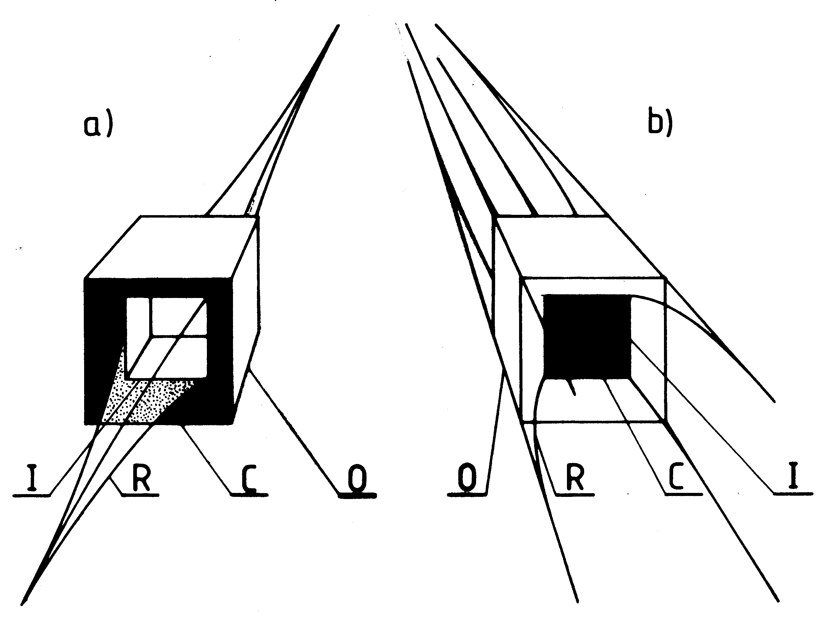
Fig. #8ab (F8(2s) and F11(2s) in [1/5]):
Two basic configurations in which for the
improvement of controllability are coupled Oscillatory Chambers,
namely the so-called (a) "twin-chamber capsule", and (b)
"spider configuration". Because at the majority of illustrations
from this web page were shown cubical Oscillatory Chambers
of the first generation, the above configurations are illustrated
on the example of coupling together octagonal Oscillatory
Chambers of the second generation.
Fig. #8a (left):
Twin-chamber capsule formed from two octagonal Oscillatory Chambers
of the second generation. Twin-chamber capsule is the basic configuration
of Oscillatory Chambers, combined together in order to increase their controllability.
It is formed from two oppositely oriented chambers placed one inside the other.
Because of the need for free floating of the inner (I) chamber suspended inside
of the outer (O) one, the side edges "a" of both Oscillatory Chambers must meet
the equation: ao=ai(sqrt(3)). The resultant magnetic flux (R) yield to the environment
from these arrangements is obtained as a difference between outputs from chambers
having opposite orientation of poles. The principles of forming this resultant flux are
illustrated in Figure F7 of [1/5]. The twin chamber capsule allows full control over
all the attributes of the produced magnetic field. The subjects of control are the
following properties of the resultant flux (R): (1) strength of the field (fluently controlled
from zero to maximum), (2) Period (T) or frequency (f) of pulsations, (3) ratio of the
amplitude of the field's pulsations to its constant component (dF/Fo - see Figure F12
in [1/5]), (4) character of the field (i.e. constant, pulsating, alternating), (5) variation in
time (i.e. linear, sinusoidal, beat type curves), (6) polarity (i.e. from whichever side
of the arrangement the N and S poles prevail).
Fig. #8b (right):
Standard spider configuration of the second generation. This configuration is
mainly used as a propulsor for the four propulsor spacecraft - see "Fig. #7". It is
formed from 1 main and 8 side Oscillatory Chambers.
The eight cubical side chambers (marked U, V, W and X) surround the oppositely
oriented main chamber (marked M) which is four times longer. The total volume of
all eight side chambers must be equal to the volume of the main one. This arrangement
is the simplified model of the Magnocraft's propulsion system. The resultant magnetic
flux (R) yield to the environment from the spider configuration is obtained as a difference
between outputs from the main chamber and the oppositely oriented side chambers.
The principles of forming this resultant flux are similar to those illustrated in "Fig. #7".
The spider configuration, similar to the twin chamber capsule, also allows full control
over all the attributes of the produced magnetic field. But in addition, the spider configuration
can spin the produced field around its magnetic axis "m" thus producing its own magnetic
whirl. Its main drawback in comparison to the twin-chamber capsule is the lack of ability
to complete "extinguish" the magnetic field yield to the environment (even if the entire
output of this configuration is bound into the circulating flux (C), still this flux will circulate
via the environment).
Part #E:
Evidence which confirms that magnetically propelled flying vehicles are technically feasible and are going to be constructed:
As it turns out, the
Magnocraft
is not just a product of imagination. Actually it turns out that this vehicle
is already flying above Earth. People describe it under the name of
UFOs. In order to realise how close is the appearance of and
thus also the operation of a UFO and the Magnocraft, have a look at
the following two illustrations. The upper one of them presents a
photographs of a UFO type K3. In turn the lower one presents a drawing
of the Magnocraft shown from the same angle us this UFO. Here are they:
Fig. #9ab (P1 in [1/5]):
The comparison of shape of a discoidal UFO type K3
with discoidal Magnocraft type K3 of the first generation. In order to facilitate
this comparison, the Magnocraft shown before in Fig. #2 is here slanted
to obtain approximately the same orientation as the UFO vehicle has.
Fig. #9a (left):
A K3 type of the flying vehicle popularly known as a UFO.
(The photographs shown above is also shown and explained
in Figure P1 from volume 14 of the newest monograph [1/5],
as well as in Figure J1 from older monograph [1e], and in
Figure K1 from older monograph [2e].)
Such UFO vehicles use exactly the same type of magnetic
propulsion system as the one utilised by the Magnocraft.
Fig. #9b (right):
The appearance of the smallest Magnocraft type K3
illustrated in the position as the UFO from Fig. #4a.
(The drawing shown above is also shown and explained
in Figure P1 (framed) from monograph [1/5], in Figure
G4 from monographs [1e], and also in Figure G4 from
monograph [2e] - all three monographs are downloadable
free of charge from this web site). The Magnocraft type
K3 is the one for which the ratio K of the outer diameter
"D" to the total height "H" is equal to K=D/H=3 (hence
the name K3).
Please notice that the above illustration is also discussed
on "Fig. #11ab" and "Fig. #12" from the totaliztic web page
tapanui.htm -
where the reader can learn further details about both
vehicles illustrated here.
#E2.
The
formal scientific proof,
that "UFOs do exist and they are already operational Magnocrafts":
There is a formal scientific proof already
developed and published, stating that
"UFOs do exist and they are already operational
Magnocrafts".
This proof is published in subsection P2
from volume 14 of my newest
monograph [1/5]
(and also in chapter J from older monograph
[1e]). A brief summary of this formal proof is
published on the totaliztic web page named
ufo_proof.htm.
This proof discloses why UFOs and Magnocraft
must have identical propulsion system, shape,
capabilities, and attributes. Furthermore, it provides
a powerful tool for the understanding attributes and
operation of UFOs. It is so because everything that
we know about the Magnocraft we can at present
apply also to UFOs. It is because of this knowledge
of the Magnocraft that e.g. the details of the
UFO explosion near Tapanui
could be researched and identified so thoroughly.
Also because of this proof, in 2003 the Magnocraft
was voted by members of the internet discussion
forum as the explanation for technical aspects of
UFOs - for details see the resolution discussed in
item #J2 from the web page named
explain.htm.
and in item #D2 from the web page named
timevehicle.htm.
This formal proof was accomplished with the use
of extremely reliable formal scientific methodology
called the "method of matching attributes".
This method is described in subsection P1
of the abovementioned my
monograph [1/5].
It later becomes the methodological basis for the
completion for the first time in the world of several
further formal proofs by the author of this web
page. All these proofs are listed in item #G3 from
the web page named
god_proof.htm.
Together all these proofs try to repair negligence
and deviations which with the elapse of time grew
up around our official science.
Since no-one managed to abolish this formal proof
for the existence of UFOs, this proof remains
in power all the time, and it should terminate the previous period
of arguing about the existence, or non-existence, of UFOs. Now we
should start the period of time when we thoroughly research these
extraterrestrial vehicles and their evil crew members. After all,
such researching of UFO technology may accelerate on Earth the
completion of technical devices which UFOnauts already use, but
which still remain unknown for our civilisation. Examples of such
devices include: magnetic propulsors, telepathic communication
devices, time vehicles, moral energy extractors, and many more -
for details see subsection D10 in monograph [8] downloadable from
this web site. In turn researching evil crew members of UFO vehicles
will accelerate our understanding reasons why UFOnauts exploit people,
and help humanity to free itself from claws of these cosmic parasites.
As it turns out the Oscillatory Chamber
invented in order to propel the
Magnocraft,
are already used by UFOs.
There are even photographs of these devices taken on UFOs. Here are
two photographs of the square outlets from the cubical Oscillatory
Chambers of UFOs, published in Figure S5 from chapter S of monograph
[1/5]. Notice that because of the right one of these two photographs
is taken during the night, the black square in the centre of the outlet
blends with the black background of the sky. Below these two photographs,
the predicted appearance of outlets from Magnocraft's oscillatory
chambers is also illustrated.
Fig. #10abcd (S5ab and F6 in [1/5]):
Two photographs which captured the appearance
of outlets from Oscillatory Chambers of UFOs of the
first generation. In order to illustrate what each photograph
represents, the lower row shows Oscillatory Chambers of
the Magnocraft operating in the same modes.
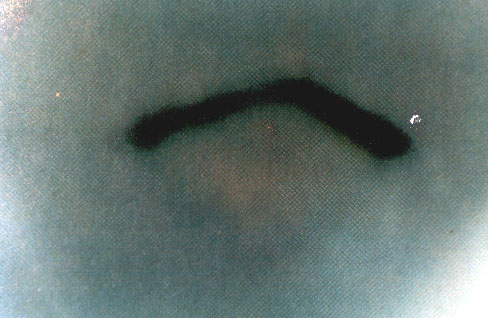
Fig. #10a (Top - left):
A day-time photograph of the outlet from
the main Oscillatory Chamber of a UFO vehicle which
operated with the inner flux prevalence.
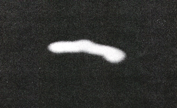
Fig. #10b (Top - right):
A night-time photograph of the outlet from
the main Oscillatory Chamber of a UFO vehicle which
operated with the outer flux prevalence.
Fig. #10cd (Bottom left and right):
Drawings of outlets from Oscillatory Chambers
used in Magnocraft of the first generation,
which operated in the same modes as these
captured on photographs shown above them.
By realising that the Oscillatory Chamber is
already build and used by UFOnauts, we accomplish
a reassurance that our completion of this device is feasible and
that it bears a potential for a certain success - if we decide
to construct it. Therefore we should roll our sleeves up, and
start to complete this revolutionary device. After all, it not
only is able to lift us to the stars, but also allows to free
ourselves from the occupation by evil UFOnauts.
Please notice that the above illustration is also
discussed on "Fig. #13abcd" from the totaliztic
web page
tapanui.htm
where the reader can learn further details about the
appearances of the Oscillatory Chambers illustrated
here.
#E4.
Because of the amount of energy that UFOs accumulate in their Oscillatory Chamber, UFOs are actually flying bombs:
Of course, the fact that UFOs utilise
Oscillatory Chamber
for their propulsion, combined with the fact
that Oscillatory Chambers can accumulate
in themselves enormous amounts of magnetic
energy, introduces certain dangers for our
civilisation. Namely, each UFO vehicle is
actually a flying bomb, which only awaits
to explode. In subsection G5.5 of monograph
[1/5] the amount of magnetic energy carried
out in a smallest K3 type UFO is calculated.
It turns out that just in order to lift itself from
the surface of Earth, such a smallest UFO
must have accumulated in its Oscillatory Chambers the magnetic
equivalent of 1 megaton of TNT. But this 1 megaton of TNT does not account
for acceleration and for flights in free space. In reality such a smallest
UFO may have accumulated even 1000 times more magnetic energy, amounting
to an equivalent of around 1000 megaton of TNT. This practically means
that if there is any accident involving such a UFO vehicle, and if
Oscillatory Chambers of this vehicle are accidentally damaged, then
we must expect a catastrophic explosion of the magnitude of at least
1 megaton TNT. Practically this indicates, that if there actually was
a UFO accident of 1947 in Roswell, USA, as American UFOlogists claim
this, then almost the entire America would be wiped out in the result.
So there wouldn't be any American UFOlogist left in there to claim the
actual occurrence of such a UFO accident.
More information about the use of UFOs as
flying bombs is provided in item #B1 of the
web page named
military_magnocraft.htm.
#E5.
UFO explosions:
Since UFOs are flying bombs loaded with
magnetic energy and only awaiting to explode,
we should expect that there were already
various UFO explosions on Earth. As it turns
out, YES. Actually there were numerous UFO
explosions on Earth. About several of them
I wrote my monographs from the series
[5] -
which can be downloaded free of charge via this
web page. I also prepared a separate web page
tapanui.htm,
which presents evidence and consequences
of a UFO explosion that occurred near a small
New Zealand township named Tapanui.
This Tapanui explosion of UFOs turned out to
be especially tragic to humanity. As research
indicate, it probably wiped a significant proportion
of population of Earth of that time. It also practically
destroyed flourishing human civilisations of antiquity,
turning the beauty and prosperity of ancient empires
into darkness, sickness, and death of medieval
period of Earth's history. Out of specific changes on our planet that this
UFO explosion from Tapanui caused and that can be noticed by everyone, the
most important include: the shifting of Earth's poles by around 7 degrees,
the freezing of previously green Greenland together with the Viking colony
in there, the melting of ice bridge in the Bering Straights - which before
1178 allowed Eskimo people freely travel on dry ice between Siberia and Alaska,
flooding Schlezwig-Holstain in Germany, destruction of ancient Salamis, leaning
the famous "Leaning Tower" from Pisa in Italy, and many more - for further details see
tapanui.htm.
The most recent, however, underground
explosion of a UFO vehicle took place on 26th December 2004. It occurred near
the island of Sumatra on the Indian Ocean. It caused one of the most powerful
tsunamis in recent history. Many people took it for a natural disaster. But the analysis
of attributes of it, provided on the separate web page entitled
"day26.htm",
proves that it had a technological origin from a UFO explosion. For more details
about this most recent UFO explosion - see the web page
"day26.htm",
available through
"Menu 4" or/and
"Menu 2".
#E6.
If UFOs are Magnocraft, then why UFOnauts do not give us their technology:
It turns out that UFOnauts
are actually our enemies. They exploit us and draw countless
benefits from our planet. But at the time when we accomplish
their level of technology, UFOnauts loose all these benefits.
Therefore they not only do not allow us to have their technology,
but actually they hide from us practically everything, including
their continuous presence on Earth. Furthermore, as all oppressors
do, UFOnauts hold back our development, e.g. by hidden murdering
our best brains. Therefore practically we need to bit UFOnauts
militarily, in order to free our civilisation from their hidden
occupation. But in order to start fighting with UFOnauts, we
firstly need to build our
Magnocraft.
Only then our technical
level become equal to theirs, so that we start having a chance
with fighting them out from our planet. If we believe in ancient
prediction, e.g. ones which are described in the Bible, the time
is coming now, when we start to defend ourselves successfully from
UFOnauts. Only when we remove these oppressors from our planet,
on Earth these promised 1000 years of prosperity and happiness
is going to prevail. For more details on UFOnauts see the web
site
ufo.htm.
Part #F:
Further generations of magnetically propelled flying vehicles which are even
more advanced than Magnocraft of the first generation described earlier:
#F1.
Three generations of
Magnocraft
which according to the Cyclic Principle are
to be completed at the Earth in the future:
Two most advanced flying vehicles that are
predicted by the "Cyclic Principle" as being
build right after the Magnocraft of the first
generation, will represent just slightly more
advanced versions of that Magnocraft already
described and illustrated in item #C1
of this web page, while fully explained in
chapter G from volume 3 of monograph [1/5]
(briefly summarized also in subsection C1 of that
monograph [1/5]).
Only that, according to the "Cyclic Principle",
their propulsors will be able to generate these
two additional phenomena, i.e. technically
induced telekinesis, and changes in the elapse
of time. For this reason these two vehicles are
called the Magnocraft of the second generation,
and the Magnocraft of the third generation.
So together with the Magnocraft of the first
generation described in item #C1 above,
our civilization is going to build three generations
of this vehicle, in each subsequent generation
utilizing increasingly more complex attributes
of magnetic fields. Let us briefly summarize
now characteristics of these vehicles.
#F1.1.
The
Magnocraft
of the first generation with the propulsion system which operates on principles of magnetic repulsion and attraction:
The Magnocraft of the first generation is
already described briefly in item #C1 of
this web page, as well as in subsection
C1 from volume 1 of
monograph [1/5].
That "Magnocraft of the first generation",
called also the "Discoidal Magnocraft",
or simply "Magnocraft", will be build
firstly on our planet amongst all three
these highly advanced flying vehicles
of our future. For purposes of propelling
it is going to use just only the repulsive
and attractive interactions of magnetic
fields. These interactions represent the
equivalent of mechanical force interactions
utilized in the car’s wheel, or the buoyancy
of gases utilized in operation of balloons.
Describing the Magnocraft of the first
generation with the use of technical
terminology from subsection #B5 of
monograph [1/5], this vehicle can fly
in just one convention, namely in (1)
the "magnetic convention".
#F1.2.
The
Magnocraft
of the second generation with the propulsion system which operates on principles of
telekinesis:
The "Magnocraft of the second generation"
(telekinetic vehicle) is described in subsection
LC2 from volume 10 of
monograph [1/5].
After the completion of the Magnocraft of the first generation,
the humanity is going to build also that
Magnocraft of the second generation -
sometimes called the "telekinetic vehicle".
The Magnocraft of the second generation
was not discussed yet in this web page,
so for details of it the reading of chapter
LC from volume 10 of monograph [1/5]
is recommended, while examples of the
use of it are provided in chapter T from
monograph [1/5]. In flights it will be utilizing
additionally the magnetic equivalent of
inertia, means the phenomenon called
"telekinesis" which manifests itself in the
manner as this would be done by the
reversal of friction. Because the "Concept
of Dipolar Gravity" states that on just such
a magnetic inertia is based the so-called
"Telekinetic Effect", thus the Magnocraft
of the second generation will fly utilizing
exactly the same principle which causes
the telekinetic motion. In this way the
operation of it becomes similar to other
known propulsion systems, the principles
of which were based on the utilization
of inertia, e.g. to hovercraft or to the
aircraft propeller.
Describing the Magnocrafts of the second
generation with the use of technical
terminology from subsection #B5 of monograph
[1/5], these vehicles can fly in two different
conventions, namely in (1) the "magnetic convention",
and in (2) the "telekinetic convention". In (1) the "magnetic
convention" their propulsors generate only
the phenomena of magnetic attraction and
repulsion. Thus in the sense of principles
of operation they use for flights, they become
almost identical to the Magnocrafts of the
first generation (described in chapter G of
[1/5]). Also all other phenomena that they
then induce will be identical to these induced
by Magnocrafts of the first generation.
In turn in (2) the "telekinetic convention"
their propulsors generate additionally
the phenomenon of "technical telekinesis".
Thus, then they fly in the result of the
"Telekinetic Effect" action. After
this convention of flight is switch on,
these vehicles and their crews are
getting into the state which the
Concept of Dipolar Gravity
calls the "state of telekinetic flickering".
In this state the material objects subjected
to it switch on (flicker) very fast between
two forms of their existence, namely
between the material form and the form
of energy pattern. (More comprehensively
this state is is explained in subsection LC3
from volume 10 of monograph [1/5].)
It is this "state of telekinetic flickering" that
allows these vehicles to become completely
invisible to human sight and cameras,
and also allows them to penetrate through
solid objects as if these solid objects
are made of an easily penetrable liquid
instead of a stiff matter.
"Magnocrafts of the third generation"
(i.e. time vehicles) are described in
chapter M from volume 11 of
monograph [1/5],
and also on several web pages indicated
here. At the very end the Magnocrafts'
development, Magnocrafts of the third
generation are to be build on the Earth.
These starship are also to be called the
"time vehicles". These kinds of Magnocrafts
also were not discussed on this web page,
thus readers wishing to learn more
details about them should look at their
presentation contained in chapter
M from volume 11 of monograph [1/5],
or in web pages indicated here.
In turn examples of the use of these
spaceship are presented in chapter
T of monograph [1/5]. Magnocrafts
of the third generation will utilize three
attributes of magnetic fields, namely
(1) forces of magnetic interactions,
(2) inertia, and (3) internal energy.
Because the mastery of internal energy
of magnetic fields allows for the
manipulation on time, the Magnocrafts
of the third generation will have
the ability to travel through time
(in addition to travel through space).
Let us try to describe the Magnocrafts of the
third generation with the use of technical
terminology from subsection #B5 of
monograph [1/5]. These vehicles can
fly in three different conventions, namely
in (1) the "magnetic convention", and (2) "telekinetic
convention", and additionally also in
(3) the "convention of time vehicles".
So independently of the ability to fly
in the magnetic and telekinetic conventions,
they are also able to fly in the "convention
of time travel". In this convention their propulsors
generate changes in the speed of the
elapse of time or phenomena of shifting
someone to another point in time. For
example, they will be able to shift time
back, change time to any selected
point in past or future, slow time down
or accelerate time, etc. Time vehicles
will generate a whole range of unique
phenomena related to time, the most
important of which are discussed in
subsection M5 from volume 11 of
monograph [1/5].
A more comprehensive presentation of work and
capabilities of time vehicles is provided on the
totaliztic web pages named
immortality.htm and
timevehicle.htm.
#F1.4.
Identification of the generation of a
Magnocraft
(or a
UFO) that one sees,
from the appearance or from principles of operation of a given space vehicle:
At this point it should be emphasized, that
for a person unfamiliar with appropriate
theoretical foundations, the appearance
of Telekinetic Vehicles and Time Vehicles
will be identical to the appearance of an
ordinary Magnocraft of the first generation.
Therefore such a person will not be able
to distinguish between these vehicles of
different generations, and thus also to
prepare himself or herself to a type of
phenomena that he or she may face in
their presence. All three generations of
these vehicles will have exactly the same
shapes, dimensions, range of types, and
will also be constructed from materials
displaying almost the same visual
characteristics. For the duration of flights
all these vehicles will also couple into
the same flying arrangements - see
Figure G6 from [1/5]. Furthermore,
their mutual similarity will be reinforced
additionally by the fact that the Magnocraft
of the second and third generation will be
able to switch their operation onto the
magnetic convention of flights, thus
displaying the same range of phenomena
that an ordinary Magnocraft does.
The differences existing between
them become apparent only when
they switch on their most advanced
convention of the flight, inducing in
that way the phenomena characteristic
for just the second or the third generation
of magnetic propulsion systems.
For an expert this difference will
become also visible from some
technical details (e.g. from the shape
of their Oscillatory Chambers - see
subsection F3 of [1/5]).
Fig. #11abc (LC1 in [1/5]):
Identification of the generation of Four-Propulsor Magnocraft
(or four-propulsor UFO) that one sees, on the basis of
the appearance of the entire vehicle or the appearance
(and thus also the generation) of its magnetic propulsors.
This illustration is oriented towards allowing one to distinguish between
quite similar four-propulsor vehicles of the first, second, and third
generation. These vehicles most frequently takes a shape of a cubicle,
on the top of which a pyramidal roof is placed. But notice that these
vehicles can also be build in shapes different from cubicles, e.g. looking
like rectangular huts. The mutual ratio of subsequent dimensions, e.g.
the height of the entire vehicle to the height of its pyramidal roof, is defining
the type of this vehicle - in this case T3. (This ratio is also illustrated in "Fig. #7".)
The span of magnetic axis of four propulsors mounted in the mid-height
of four corners of this vehicle must be identical to the span of side propulsors
in the equivalent type of Discoidal Magnocraft (in this case - in the type K3).
Shown are:
Fig. #11a (left):
#1. Four-propulsor vehicle of the first generation (magnetic). (see also "Fig. #7").
Propulsors of this vehicle take the shape of vertically prolonged barrel or
amphora, in which the ratio of height "h" to width "g" is equal to h/g=4/3
(see also Figures D1 and F9 of [1/5]). Also this is the only four-propulsor
vehicle, which has square "doors" in the floor.
Fig. #11b (centre):
#2. Telekinetic four-propulsor vehicle of the second generation.
It can be distinguished relatively easy from similar vehicles of other
generations by the "pumpkin" shape of the four propulsors. In vehicles
of the second generation these propulsors take very characteristic shape
of the sphere flattened vertically (or a "pumpkin") with the mutual ratio
of the height "h" to width "g" equal to h/g=2/3 (see subsection F7.2.2
and part 2s from Figure F11 of [1/5]). This shape results from the design
conditions prevailing for spider configurations constructed from octagonal
oscillatory chambers of the second generation described in subsection
F7.2.2 of [1/5]. In addition to the difference in the general appearance,
the vehicle of the second generation is also going to have absolutely
smooth hulk, deprived of any portholes or doors. So it is NOT going
to have neither a doorway shown in part (1) and in "Fig. #7", nor the
floor doors visible in Figure Q1 of [1/5]. The entering of crew, passengers,
and visitors on the board of vehicle of the second generation is going
to be carried out in a telekinetic manner, through the material of the
walls and floors. So no doors or portholes will be needed neither in walls nor in the floor.
Fig. #11c (right):
#3. Four-propulsor vehicle of the third generation,
called also "four-propulsor time vehicle". It also
does not have doors nor portholes. The propulsors
of it take the striking appearance of a vertical cylinder
with the ring of 16 holes around peripherals of it, looking
like a kind of "round launcher of rocket missiles" -
see also Figures LC1 and F11 (3s) from monograph [1/5].
Part #G:
Summary, and the final information of this web page:
#G1.
Summary of this web page:
Our civilisation develops continually. To this
development are also subjected propelling
devices which the humanity uses. This web
page described the most important amongst
such propelling devices, which should appear
on our planet in not-too-distant future.
#G2.
Read also about free energy:
Since you are interested in new technical
developments, you should also have a look
at the web page describing the design and
operation of devices for generating the so-called
free energy.
The most promising amongst these free
energy devices are so-called
telekinetic cells
which are to be also utilised for energy supply
of space vehicles described on this web page.
Addresses of pages on free energy are provided in
"Menu 2" or
"Menu 4".
Current email addresses to the author of
this web page, i.e. officially to
Dr Eng. Jan Pajak
while courteously to Prof. Dr Eng. Jan Pajak,
at which readers can post possible comments,
opinions, descriptions, or information which in
their opinion I should learn, are provided on the web page named
pajak_jan_uk.htm
(for its version in the HTML language), or the web page named
pajak_jan_uk.pdf
(for the version of the web page "pajak_jan_uk.pdf"
in safe PDF format - which safe PDF versions
of further web pages by the author can also be
downloaded via links from item #B1 of the web page named
text_11.htm).
The author's right for the use of courteous
title of "Professor" stems from the custom that
"with professors is like with generals", namely
when someone is
once a professor, than he or she courteously
remains a professor forever. In
turn the author of this web page was a professor
at 4 different universities, i.e. at 3 of them,
from 1 September 1992 untill 31 October 1998,
as an "Associate Professor" from English-based
educational system, while on one university as
a (Full) "Professor" (since 1 March 2007 till
31 December 2007 - means at the last place
of employment in his professional life).
However, please notice that because of my
rather chronic lack of time, I reluctantly
reply to emails which contain JUST time
consuming requests, while simultaneously
they document a complete ignorance of their
author in the topic area which I am researching.
#G4.
How with the web page named
"skorowidz_links.htm"
one can find totaliztic descriptions
of topics in which he is interested:
A whole array of topics equally interesting
as these from the above web page, is also
discussed from the angle that is unique to
the philosophy of totalizm. All these related
topics can be found and identified with the use of
content index
prepared especially to make easier finding
these web pages and topics. The name "index"
means a list of "key words" usually provided
at the end of textbooks, which allows to find
fast the description or the topic in which we
are interested. My web pages also has such
a content "index" - only that it is additionally
supplied in green
links
which after "clicking" at them with a mouse
immediately open the web page with the topic
that interest the reader. This content "index"
is provided on the web page named
skorowidz_links.htm.
It can be called from the "organising" part of
"Menu 1" of every totaliztic web page. I would
recommend to look at it and to begin using it
systematically - after all it brings closer hundreds
of totaliztic topics which can be of interest to
everyone.
This web page is also available in the form
of a brochure marked [11], which
is prepared in "PDF" ("Portable Document
Format") - currently considered to be the
most safe amongst all internet formats, as
normally viruses cannot cling to PDF. This
clear brochure is ready both, for printing,
as well as for reading from a computer
screen. It also has all its
green links
still active. Thus, if it is read from the computer
screen connected to internet, then after clicking
onto these green links, the linked web pages
and illustrations will open. Unfortunately, because
the volume of it is around a double of the volume
of web page which this brochure publishes,
the memory limitations on a significant number
of free servers which I use, do NOT allow to
offer it from them (so if it does NOT download
from this address, because it is NOT available
on this server, then you should click onto any
other address from
Menu 3,
and then check whether in there it is available).
In order to open this brochure (and/or download
it to own computer), it suffices to either click on
the following green link
or to open from any totaliztic web site the
PDF file named as in the above green link.
If the reader wishes to check, whether some other
totaliztic web page which he or she just is studying,
is also available in the form of such PDF brochure,
then should check whether it is listed amongst links
from "part #B" of the web page named
text_11.htm.
This is because links from there indicate all totaliztic
web pages, which are already published as such
brochures from series [11] in PDF format.
I wish you a fruitful reading!
Jesli mowisz po polsku,
kliknij na polska flage (if you prefer reading in Polish
click on the Polish flag)
Date of starting this page: 28 April 2002.
Date of the latest updating of this page: 7 October 2013
(Check in "Menu 3" whether there is even a more recent update!)